HVAC — heating, ventilation, air conditioning
Heating and cooling loads, equipment selection, ductwork and pipework.
We calculate loads on real operating profiles and select equipment that performs at part load, not only at peak.
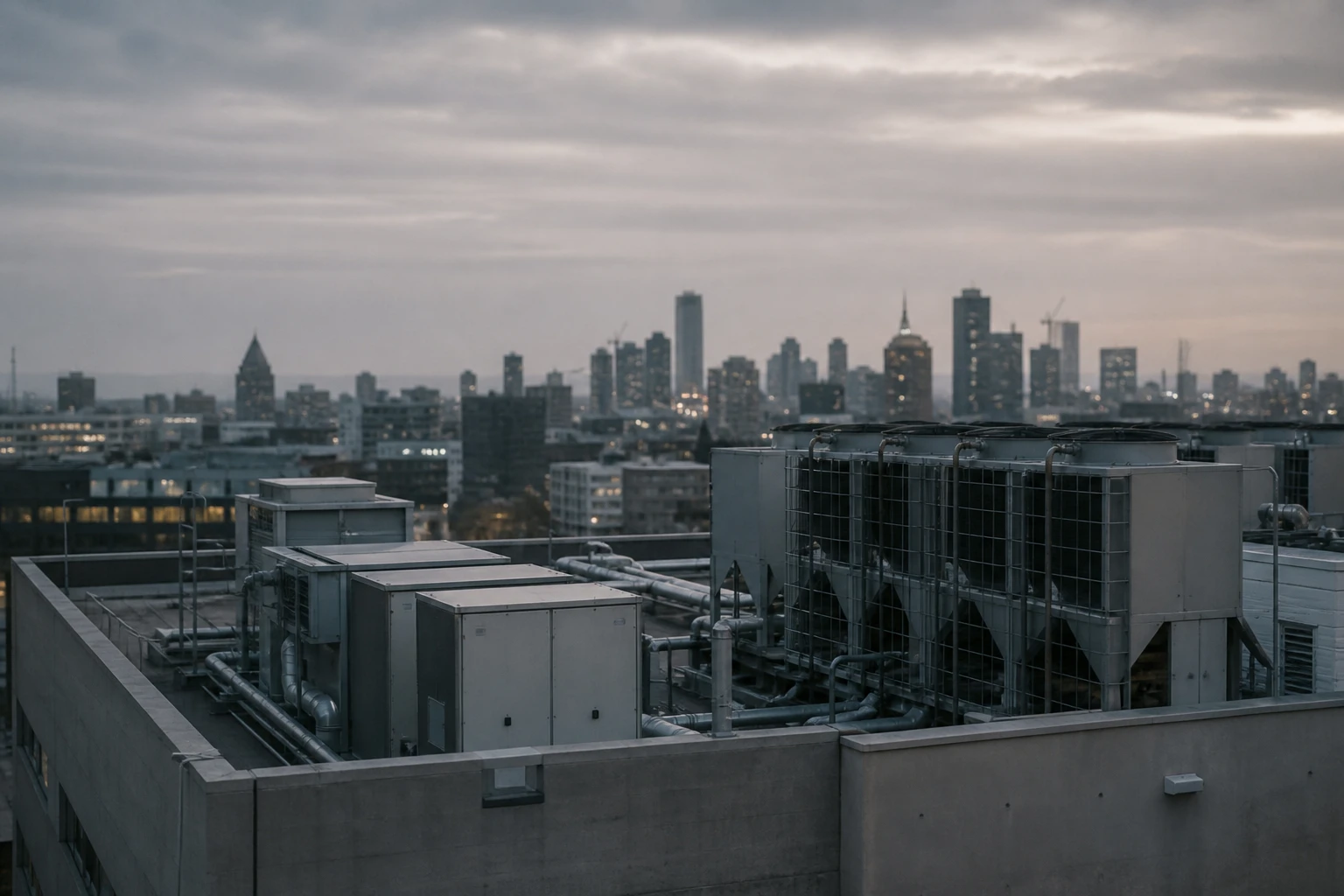
Heating and cooling load calculations to EN 12831 and ASHRAE methods
Heating scheme: heat source, substation, circuits, balancing
Ventilation: air change by room function, heat recovery, smoke extract
Air conditioning: VRF, chiller–fan coil or split, with comparison and rationale
Kitchen and sanitary extract systems
Noise and vibration control: attenuators, anti-vibration mounts, routing
Design report with load calculations
Plans with ductwork and pipework
Plant room and substation details
Equipment schedule with parameters
Bill of quantities for procurement
Balancing schedule for commissioning
Hotels
Residential
Offices
Restaurants
Clinics
EN 12831
EN 16798-1
ASHRAE 62.1
ASHRAE 90.1
Not enough ceiling void for ductwork
We switch to flat sections, split the load across two systems or change the scheme. The decision is made in the model, not on site.
Safety margins inflate the budget
We recalculate on actual occupancy and operating hours. Equipment often drops one size.
Cold in winter, noisy in summer
We check balancing and supply air velocity; the problem is usually regulation, not capacity.
VRF or chiller?
It depends on area, zoning and servicing. Below 3,000 m² usually VRF; on larger buildings chiller–fan coil. We provide a cost-of-ownership comparison.
Is heat recovery worth it?
Where ventilation runs continuously, yes — it returns through the heating bill.
Can you audit an existing system?
Yes, we measure flows and temperatures and issue a list of what needs to change.
Process
Survey and brief
We measure what exists: available capacity, pipe sizes, slab-to-ceiling heights, routing of services. We write the brief, the client approves it.
Concept and load calculations
Heating and cooling loads to EN 12831, electrical balance, water demand. This is where the kW and m³/h you will request from utilities are fixed.
Schematic design
Equipment layout, plant room areas, main shafts and routes. Agreed with the architect before the façade and ceilings close.
Detailed design
Plans, schematics, details, specifications and bills of quantities. Clashes are resolved in the model — pipe and duct meet on screen, not on site.
Technical conditions and approvals
Applications to utility companies, fire section review, closing of comments. We keep a log of what was submitted and when.
Tender and suppliers
We issue a procurement sheet with technical parameters and compare offers on service and spare-part availability, not price alone.
Site supervision
Scheduled visits, hidden-works records, change tracking. An installation error is corrected while the ceiling is still open.
Commissioning and handover
Air and water balancing against design, interlock testing, as-built documentation and an operating manual for the facility team.
Quote request
Leave your phone number; the relevant division will contact you.
+995 591 558 585WhatsApp · +995 591 558 585